Because of the ill-conditioned nature of arithmetic relating to coordinate transformations, descriptive parameters are kept in double precision (identifier tokens and dimensioning parameters being of course integers).
Grids and coordinate systems (map projections) are
named entities, for purposes of unambiguous tracking and
database storage. Names are CHARACTER*16 strings
(consistent with the rest of the "name" objects manipulated
within the I/O system). There are finite (and extensible) lists of
names of coordinate systems and of grids currently in use within the
Models-3 system. I would not anticipate that we should need more than a
few thousand such grids. So that they are fully self-contained, both
names and complete descriptions for grids and coordinate systems (as
specified below) are kept in file headers, and stored also in file
description data structures in
FDESC3.EXT or
fdesc3.h .
There is a software subsystem for manipulating map projections, grids, and coordinates (see the User-Manual section on Coordinate and Grid Related Routines). An implementation of grid parameter access capabilities is given by the DSCGRID() routine, which reads its accompanying ASCII data file GRIDDESC.
A sample GRIDDESC file describing the main computational grids for the SMRAQ regional seasonal modeling effort (part of the Southern Oxidant Study), the OTAG study, all of the standard ROM AQM computational grids, and all of the standard Urban Airshed Model computational grids is available.
Capabilities of this software subsystem include the following:
NOTE: Longitudes are presumed to be in the range
[-180,180]. This is consistent with duly-enacted ISO
Standard 6709, treaty obligations since 1878, and several centuries of
common usage (as well as virtually all of the currently available GIS or
mapping software). Beware that the WMO with its GRIB "standards"
violates all of these. When you deal with WMO "longitudes",
you will have to write special-purpose modeling-code hacks to transform
longitude-values into ISO-6709 compliant form. Plotting WMO-style
data against a map will be particularly troublesome; sorry.
The following types of coordinate systems are
supported.
They are identified by the use of
"magic number" token values as the GDTYP3D
in file description data structures such as those found in FDESC3.EXT . The magic numbers
are specified in PARMS3.EXT, which gives their
names as LATGRD3, LAMGRD3, MERGRD3, STEGRD3, UTMGRD3, POLGRD3,
TRMGRD3, EQMGRD3, ALBGRD3, and LEQGRD3 They may be
identified by the corresponding map coordinate identifier, and further
specified by five additional descriptive parameters
PROJ_ALPHA, PROJ_BETA,
PROJ_GAMMA, X_CENT, and Y_CENT.
Note that file descriptions contain all of these specifying parameters,
so that the files are self-contained and do not require additional
grid-description support software systems.
| TYPE | ID | PARAMETERS |
|---|---|---|
| Lat-Lon | LATGRD3 = 1
|
PROJ_ALPHA, PROJ_BETA, PROJ_GAMMA unused.
ISO 6709 compliant: coordinate units are degrees, -90.0 < X ≤ 90.0 and -180.0 < Y ≤ 180.0 GCTP projection 0. Note that Western hemisphere longitudes and Southern Hemisphere latitudes are taken to be negative. Note further that, in violation of treaty obligations and duly enacted international standards, and contrary to basically all the GIS software on the plaanet, the WMO insists upon a different, 0.0 < Y ≤ 360.0 interpretation of latitude for, e.g., GRIB files. This causes substantial difficulty for modelers. |
| Lambert Conformal Conic | LAMGRD3 = 2
|
PROJ_ALPHA ≤ PROJ_BETA are the two latitudes which
determine the projection cone; PROJ_GAMMA is the central
meridian.
(X_CENT,Y_CENT) are the (lon ,lat) coordinates for the center (0,0) of the Cartesian coordinate system. Coordinate units are meters. GCTP projection 4. |
| Mercator | MERGRD3 = 3
|
general Mercator
PROJ_ALPHA and PROJ_BETA are the latitude and longitude of the coordinate origin (within the tangent circle) PROJ_GAMMA is the angle between the cylinder axis and the North polar axis. (X_CENT,Y_CENT) are the (lon ,lat) coordinates for the center (0,0) of the Cartesian coordinate system. Coordinate units are meters. GCTP projection 20. |
| Stereographic | STEGRD3 = 4
|
general tangent stereographic
PROJ_ALPHA is the "true latitude", the latitude at which the stereographic plane is secant to the Earth (or 90, if the projection is a North Polar tangent stereographic. PROJ_BETA is the angle of rotation of the Y-axis relative to the Greenwich meridian, i.e., the longitude meridian which becomes the negative Y axis. PROJ_GAMMA is unused. (X_CENT,Y_CENT) are the (lon ,lat) coordinates for the center (0,0) of the Cartesian coordinate system. Coordinate units are meters. GCTP projection 10. |
| UTM | UTMGRD3 = 5
|
special case of Mercator
PROJ_ALPHA is the UTM zone, considered as a DOUBLE. PROJ_BETA and PROJ_GAMMA are unused. (X_CENT,Y_CENT) are the UTM coordinates of the origin for offset UTM coordinates (or are (0,0) for Equator-based UTM coords). Coordinate units are meters. GCTP projection 1. |
| Polar | POLGRD3 = 6
|
polar secant stereographic
PROJ_ALPHA is 1.0 for North Polar, -1.0 for South Polar. PROJ_BETA is the secant latitude (latitude of true scale), PROJ_GAMMA is the central meridian. (X_CENT,Y_CENT) are the (lon ,lat) coordinates for the center (0,0) of the Cartesian coordinate system. Coordinate units are meters. GCTP projection 6. |
| Equatorial Mercator | EQMGRD3 = 7
|
PROJ_ALPHA is the latitude of true scale.
PROJ_BETA is unused. PROJ_GAMMA is the longitude of the central meridian. (X_CENT,Y_CENT) are the (lon ,lat) coordinates for the center (0,0) of the Cartesian coordinate system. Coordinate units are meters. GCTP projection 5. |
| Transverse Mercator | TRMGRD3 = 8
|
PROJ_ALPHA is the latitude of true scale.
PROJ_BETA is the scale factor at the central meridian; PROJ_GAMMA is the longitude of the central meridian. (X_CENT,Y_CENT) are the (lon ,lat) coordinates for the center (0,0) of the Cartesian coordinate system. Coordinate units are meters. GCTP projection 9. |
| Albers Equal-Area Conic | ALBGRD3 = 9
|
PROJ_ALPHA ≤ PROJ_BETA are the two latitudes which
determine the projection cone; PROJ_GAMMA is the central
meridian.
(X_CENT,Y_CENT) are the (lon ,lat) coordinates for the center (0,0) of the Cartesian coordinate system. Coordinate units are meters. GCTP projection 3. |
| Lambert Azimuthal Equal-Area | LEQGRD3 = 10
|
PROJ_ALPHA is the central latitude; PROJ_GAMMA is the central
meridian.
(X_CENT,Y_CENT) are the (lon ,lat) coordinates for the center (0,0) of the Cartesian coordinate system. Coordinate units are meters. GCTP projection 11. |
| Sinusoidal Equal-Area | SINUGRD3 = 10
Added 5/5/2015 to I/O API-3.1,-3.2. |
PROJ_GAMMA is the central meridian.
(X_CENT,Y_CENT) are the (lon ,lat) coordinates for the center (0,0) of the Cartesian coordinate system. Coordinate units are meters. GCTP projection 16. |
Note that the standard names for UTM coordinate
systems are given in the form UTM_<nn>, where
nn is the number for the UTM zone, as counted from
ZONE 1: -180.0≤LAT≤-174.0. Most of the
Eastern US would use coordinate system UTM_17, for example.
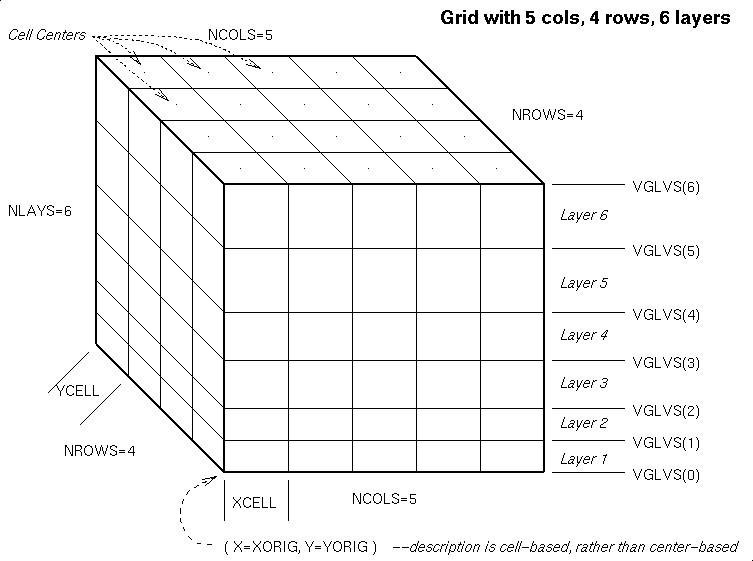
Definitions of regular grids require four descriptive parameters and two dimensioning parameters in addition to the specification of a map projection. Note that while some variables are regarded as being cell based (emissions values, considered as cell-totals, for example) and other variables are regarded as being point based (generally at the cell-centers; for example, surface temperature), the I/O API by convention uses cell-based descriptions for its grids:
Definitions of irregular and unstructured grids require a much more
complete setof descriptive parameters (e.g., the coordinates of the
grid origin and lists of cell sizes in both the X and
Y directions) in addition to the two dimensioning parameters
and map projection specifications. I do not know enough to suggest an
efficient characterization of such grids for Models-3 at this time,
although irregular grids can certainly be handled by putting the grid
geometry information into its own data file (what you might term a
"grid geometry file". Note that the grid descriptions
supported directly by the I/O API deal only with regular grids at
this time (although it allows for the later provision of irregular- or
unstructured-grid file types).
Note 1 The MPAS Earth-System model uses
unstructured Voronoi-complex grids (with their dual
Delaunay-Triangulation grids) for meteorology, land-surface, ocean, and
atmospheric chemistry modeling. The I/O API provides some high
level I/O and grid utility data structures and routines in
MODULE MODMPASFIO.
The required data structures are quite complicated :-)
Note 2 The I/O API also provides some high level
I/O routines for "raw" netCDF gridded data in
MODULE MODNCFIO.
Data files (or their generalizations) carry a complete set of parameters for both the map projection and the (regular-) grid description as attributes (e.g., within the file headers), so that the files stand alone, independent of external database or software systems. This self-description within file should be regarded as the final authority on the file's contents, since it is not subject to corruption or loss in the same way that an external system is. (Of course, this puts the demand on users that they define their files correctly). Where defining parameters are not applicable (e.g., when one is creating an irregular-grid file with an accompanying geometry file, the non-applicable parameters should be set to the standard "missing" values IMISS3 or BADVAL3 (defined in the PARMS.EXT INCLUDE file. The relationship between the defining parameters and the variables in FDESC.EXT INCLUDE file resident file description data structures is the following:
FDESC3.EXT and
fdesc3.h): vertical cordinate type specifier
VGTYP3D in FDESC3.EXT and in file
headers takes values from a short list of vertical coordinate types
with tokens for the types defined in PARMS3.EXT, as
follows:
GISLAY3, and the file-description should describe
the GIS layers in its FDESC3D field. Or for
TBLLAY3 each grid-slice may be a 2-D gridded entry in an
interpolation-table, e.g., with temperature values VGLVS3D(1)=0.0
, VGLVS3D(2)=5.0, VGLVS3D(3)=10.0, ... (degrees C) and one uses
this table to interpolate the respective variable to the (degrees-C)
2-meter air temperature.
The FDESC3.EXT
attribute NLAYS3D stores the actual number of layers in a
file. Parameter MXLAYS3 = 100 in PARMS3.EXT is used for
dimensioning an array VGLVS3D(MXLAYS3+1) in
FDESC3.EXT used to store the vertical coordinate values
for the file (up to the dimensioned maximum, although files may have
an actual number of layers in excess of this). The array section
VGLVS3D(1:NLAYS3D+1) contains valid values; subscripts in
excess of NLAYS3D+1 may well point to garbage. A new file
attribute VGTOP3D is used to store the MODEL-TOP for
the sigma coordinate types. For sigma-P coordinates, VGTOP3D is
given in Pascals; for sigma-Z, it is in meters.
Diagrams showing the relationship of the grid and its layers to the header attributes VGLVS3D, etc., are available in Postscript, X bitmap, JPEG, and GIF image formats. Note that Layer 1 is the bottom layer in the modeling grid.
VGTYP3D = IMISS is used when there is only one layer, and also when the vertical coordinate values VGLVS3D(MXLAYS3+1) are irrelevant (e.g., if the vertical coordinate value for the levels is spatially or temporally varying, in which case the values should be store as variables either in the same file or in an appropriate vertical-geometry file). In principle, layer K goes from VGLVS3D(K) to VGLVS3D(K+1). VGTOP3D is the "top of the model" parameter used for sigma types of coordinates, where generally the equation for sigma is of the form
sigma = ( X - X_top ) / ( X_bottom -X_top ).For other types of coordinate, VGTOP3D is unused, and should be set to BADVAL3.
Note that FOO < AMISS3 is a safe and machine independent test to determine whether FOO has been set to BADVAL3.
Next Section: Dates and Times and Time-increments
To: Models-3/EDSS I/O API: The Help Pages